
'S T U F F'
Concerning the etheriality of 'stuff'
More...
Retro R/C Motor Scooter (a project revisited)
Er, my wife and daughter think I'm mad, well that was the reaction as we stood surveying the plans that had just arrived last Saturday from myhobbystore.co.uk. 'What in God's name do you want to make that for? 'Why not?' Was the best answer I could muster in justification.
These folk can supply a whole catalogue of stuff, luckily for me, unluckily for my wife/assets!
I've had this scooter idea rattling around in the back of my head for years, in fact, I've already built it, many years ago. Yes, that's right, I built one back in the mid 70's, but for one reason or another, never managed to finish it properly due to the inaccessability of materials & tools (that's my excuse anyhow).

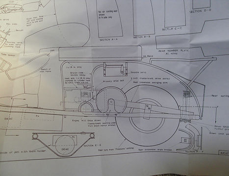
As you can see, the original (which as far as I can say, works out at about 1/3rd-1/4 scale) utilised a small diesel motor (an M.E Snipe). I think I used an E.D Bee for mine, which was not really too well suited. I think we may risk something a little more 'fruity' in this day and age? I'm thinking maybe from China perchance.
Construction is mainly aluminium alloy, I remember using old (well corroded) tv aerial material, which did the job, but was difficult to bend, being quite brittle in nature. However, I managed to fashion the frame reasonably well, and as I recall used a combination of B.A bolts & epoxy to hold it all together.
This time around, I plan on using my nice pop rivet gun, that I purchased a couple of years ago to make things a little neater. I may well invest in a model makers tap & die set as well.
I've just drawn up a shopping list, and this very eve I have sourced & ordered the main aluminium stock. This comprises, 3x900mm lengths of 10mm O.D tube (1mm wall)
1x 300mm length of 25x3mm bar
3x 125x300x1 plate
1x 300m length of 25x25x3mm angle
I've also successfully bid for two Kenning/Firestone 6" ashtray tyres on the 'bay!
Happy days :-)
Of course, in this day and age, an electric motor would be the most sensible option, clean, quiet and cheap (just like me :-)). However, that's not really quite in the spirit of things, as it'smore about recapturing the essence of the 70's, and preserving the ethos of what this little beauty was all about. Plus, I loved the way the exhaust fumes streamed from the pipe at the back. Even the 27 mhz antenna with pendant attached added extra realism to the finished product.
I think I should mention here, that on a family visit to the annual model aero 'National Championshps' (or 'Nat's' as we called them) back in the early seventies, I watched in awe as the creator, Mr J Bridge himself, demonstrated his very prototype model, one warm & balmy evening, in front of a captivated crowd of onlookers. I still remember the realistic way that rider & bike trundled around in harmony, making very realistic banking manouvers with a simple 2 channel radio setup of the day. I can clearly recall how he went on to described his processes of trial and experimentation which led him to arrive at his unique method of steering.

The Science of balance and 'gyroscopic' stuff..
It's really very simple, and it's principle is based upon his observations of how motorcycle geometry works and interacts in the real world, which is by the shifting of weight of the rider (which becomes extreme in the world of MC racing of course), in contrast to the perceived turning the handlebars, like a car steering wheel.
Obviously, his 'scooterist' was inanimate, (fabricated with the assistance of his wife no doubt, from the remnants of her sowing box!), and so was incapable of any such movements of will, so he discovered that a turn or bank could be achieved by an input or pulse from the opposite direction, innitiating a 'wobble' which caused the scooter to turn in the opposite, or in our case, the desired direction, by way of compensation. Well, that's the theory! I did get mine running, but I don't remeber how well it turned. I seem to remember it was early in the year, and so I spent several impatient weeks waiting for snow to clear from the local car park! Once cleared, the motor was the very devil to start, let alone keep running.
There are no surviving parts, so it was either broken up or sold off, post adolescence.

Unless the men in white coats head me off at the pass, I'm all set to get started, as soon as the bits & bobs start rolling in that is. I can't praise ebay enough, it really is an Aladdin's cave for these sort of projects, I'm sure it's one of the reasons my early attempt at the scooter failed, basically due to lack of affordable resources (for a 14-15 year old at least). All I need to do now is hash in the required parts. The hardest thing is deciding which one to buy!
Here's the first arrival:
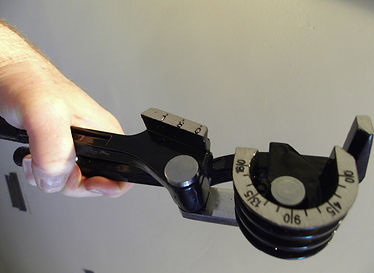
£4.99 worth of micro pipe bender. Couldn't make one for that!
Looks very easy to use, aluminium is pretty soft, so shouldn't be too difficult (he says confidently).

Now the ally has arrived, In my accustomed manner, I wasted no time in making a start. I made my first strategic 90 degree bend, at what is to be the rear of the main frame, where the two halves join. This turned out to be a mistake, as I then found it incredibly difficult to make the gradual curve that follows. Maybe it was just inexperience, there must be a way to do it like that, but I decided to start over with another of the 3x900mm lengths that I had purchased from this splendid ebayer. This time, I made gradual incremental bends every 25-30mm or so and checked progress each time with the plan.
After a while, and a little straightening and twisting, I arrived at the 90 degree bend to finish. I made sure that I had the bender in exactly the right position and applied brute force (and ignorance!). The tube bent smartly round, and I released it to double check. A couple more fractional adjustments and that was part one accomplished.
It wasn't a perfect factory produced curve, but it's fine for this project, and any inaccuracies can be bench true'd if necessary. It's not Valentino Rossi's moto GP bike after all.
Let the build begin!

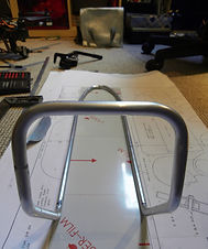
I then marked the frame where the start of the bend's should be with a permanent marker, and moved on to the second bend, as you can see on the right. Again, I took it easy, and checked after every careful bend, until it approached the correct angle, making final adjustments as necessary.
Two more bends, and one half was complete. As I say, at the weekend, hopefully when I have two identical halves, I'll take them out to the garage and get them squared up on the bench. The difficulty will be getting the bends in exactly the same position on both sides. I think I have worked out a way to do this, it's just putting it into practice that'll be the trick!
Here you can see the two sides, with the first attempt at the bottom. Actually, it looks worse at this angle than it actually is. From above, it's quite acceptable. I'll finish forming the rest of the curves first, before trimming and joining the two halves.
Whilst I was enjoying myself with the pipe bender, I couldn't help but reminisce about my early attempts, some 40 years ago, when I attempted to bend the tv antenna material. I had no tube bender to hand in those days, and the aluminium was quite brittle (doubtless from being on a roof for 20 years or so). I remember filling the tube with sand, and heating it over the gas stove. I can clearly recall the pain involved, trying to hold the hot metal with threadbare oven gloves.
Ouch! The smell wasn't particularly nice either. Still, I did have loads of the stuff to practice on, and managed it in the end.
I think with these builds, you need a certain amount of luck of the devil, and whilst looking around for some material to join the two haves together with, I clocked the 8mm carbon rod I had spare from my 'ASW 28' glider wing joiner conversion. It fitted perfectly inside the tubing, as you can see, serendipity itself ;-)
This will be keyed up and epoxied into the frame members, and should make an extremely strong joiner.


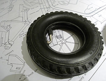
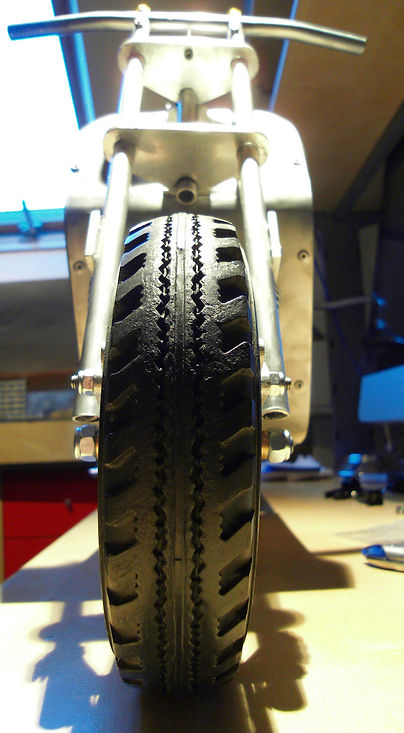
Here's the front tyre, a Kenning (not 'Town & Country' as specified by Mr B but hey-hum :-) ), with my 6" inner tube insitu. Whether or not I actually use it will largely depend on the structure and suitability of the wheels I end up with. The original does not call for them, as there is sufficient rigidity in the tyre walls for the relative light weight of the scooter. I'm just a sucker for detail!

Disaster! Well, it was all going too well to be believed. First bend of the evening should have been the third from last, but I blame tiredness for my schoolboy error. I marked the position of the bend, exactly right, then proceeded to bend the metal the wrong way!! That's when it all started to go pear shaped, as I attempted to bend it back the other way, then suddenly, snap! Horror of horrors, my second half of the frame was ruined! Now this is where it gets a bit worrying. Fair enough expecting the metal to bend back was optimism in the extreme, but what followed was disappointing. After the frustration had abated slightly, I attempted to bend a 90 degree in the same tubing, a little further down, and got to about 20 degrees, then bang! it snapped. I tried this couple of times, with the same result, and looking at the metal, it appears this piece of tubing has flaws in the structure of the metal, even the thickness of the 1mm walls looked decidedly thinner, maybe just over .75mm instead.
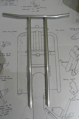
Well, I can't describe how p***** off I was, it was sooooo unfortunate, and the better of the two halves as well! That's Murphy for you though I guess. After a cup of the Earl Grey had soothed the agony, I thought I'd set about some of the more perfunctory, and so 'safer' tasks, namely; front forks, handlebars and the rear seat frame. It must be that kind of day, as straight away I messed up the 90 degree bend on the 25mmx3mm alloy bar for the seat frame! After thinking it over, I decided to use the tube bender to form the curve, which turned out to be a decent solution (for once). The curve is a little wider radius than the plan, but looks good, as it is a radiused curve as opposed to a goofy 'fold' in the metal. Uri Geller, where are you?!


So, work has ground to a halt temporarily, which is fine. After a good night's sleep, I regaled myself with the splendid progress I had made so far, plus I really need to get my butt down to the allotment over the weekend, crops don't plant themselves :-)
I don't know about you, but I find when things start going wrong, it's sometimes best to just turn your back on them for a few days, then return refreshed, and stuff that refused to work a couple of days before amazingly starts to cooperate. So that's what I'm going to do. I couldn't bear to mess up the completed half, that would be agony! I have to say, although metalwork was one of my fave subjects at school (albeit 40 years ago) I always had some shortcomings regarding accurate marking out and cutting, fact is, I love making things, but sometimes do things in haste, without proper consideration, which I regret at my leisure. I recall, the late Mr Wilson rapped my knuckles and called me a clown on numerous occasions. It's an engineering mantra, accuracy, accuracy, accuracy! Learning how to mark out correctly using the engineer's blue dye was one of first things we learned, but I always struggled with it, but it is the bedrock of the model maker.
However, I'm always willing to learn & improve, so I've ordered myself a scribe, centre punch & model engineer's calipers, oh and some 'Wiss' straight cut tin snips for that overkill effect! God bless the 'bay. I must get some decent hacksaw blades, oh and a half round file, or 10mm round as well, having the correct tools for the job is paramount.
Powerplant...
Whilst on my quest for a suitable motor to make this little thing roll, I came across this beast from good old HK. Basically, due to size restrictions, I reccon the largest motor I can get in (with the bulbous pipe) is a .07 ci. I've no idea if this is powerful enough, as the original design hailed back to the days of grunty diesels, and the M.E Snipe was 1.5cc, and .07 ci runs out at 1.147cc, I'm sure this modern Japanese nitro will produce twice the bhp of the Snipe!
Anyhow, for £69.57 delivered, I get a RTR buggy thrown in! The engine alone, sans air filter & silencer on ebay was about £50.

Success!
At last, third attempt, we have a frame. So the replacement tubing arrived yesterday, and again, I wasted no time in getting cracking on the 'crucial' bends! First length of tubing bent fine on the gentle rear curve (I'm getting quicker at it now ;-) ) then bang! it sheared on the 90 degree. Two more lengths left! I decided to try the other end of the tube first, but that sheared, so must be another dodgy flawed piece.
Anyhow, best foot forward, I gingerly began on the second piece, tapping it to see if I could spot any obvious weakness, but hey, it just sounded like aluminium to me! I'm sure the aerospace industry has some clever stuff to test for faulty metal. I started (as usual!) on the rear curve, virtually doing it blindfold. Deep breath for the 90, wait! It's bending, no snap! So far so good, I got to 45 degrees, and had visions of a huge pile of broken ally! But, joy of joys, on this occasion, the metal bending gods were smiling gracefully, and the bend was accomplished in style. Phew! Joking apart, it was becoming a real pain in the neck, something that started out pleasurable, was slowly becoming tedious.
After the elation had died down, I set about the exacting task of joining the two halves together. I do prefer the positioning of the front joint, as I originally planned to have it centrally on the top cross member, but decided to move it to the down tube both for looks and strength.
Once I'd true'd the frame work up, and cut the 8mm carbon joint pieces to fit inside the frame, epoxy was mixed, and duly applied. There's not much 'meat' in the back, as there is very little actual straight metal to work with, but better than nowt!


Here you can see the happy union. Just needs cleaning up on the joints, and a final tweak of the frame to get it as true as it can be, given my limited skills vis-a-vis metal bending and motorcycle frame manufacture. I am pleased how the two halves have mated up though, just a case of knowing when to stop really.
I was on a bit of a roll, so after the epoxy had set, I thought I'd make some progress with the other pieces I'd prepped a few days beforehand.

Here's one I made earlier...
I drilled a few holes for the pop rivets, with my less than satisfactory drills. Breaking two in the process. I must look up aluminium cutting lubrication, I seem to remember a white paraffin solution at school, or was that for mild steel?
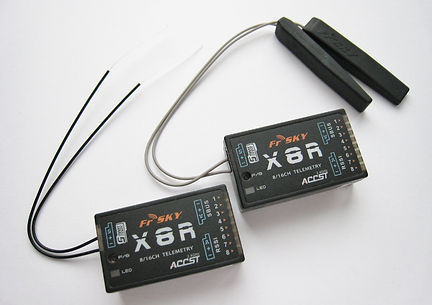
Thinking ahead (forward planning is my speciality!), I'm looking at placings for my radio gear, not much of it really these days, compared to when J Bridge built his prototype, with a hefty 'deac' (de-accumulator) for power, and probably quite a chunky Rx to boot. I'm not certain yet, but I may use my FrSKy X8R Rx, as It's going spare, and I really should get some use out of it. I'm not certain yet, but I favour throttle on the left and steering on the right. No idea what 'mode' that is though, I'll leave that one for the nerds!
Mr Bridge located his Tx & power supply below the footplate, encased in foam and another sheet of formed aluminium. I can understand why he chose that location, probably to keep the C of G as low as possible, but when you think about it, directly behind the front wheel may not be the best place regarding water penetration, although I guess his creation was not meant to endure the rigours of a daily commute like the real thing! That being the case, as it will likely be used only in dry conditions, I may stick to the original location.
Decisions, decisions!

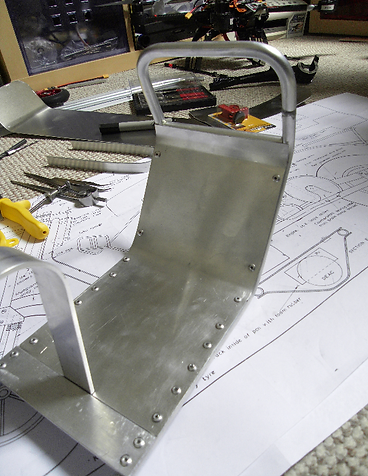
The picture so far..
On the left here we have the embryonic formation of Mr J Bridge's R/C motor scooter c.1973. Pop rivets looking cool (although they are ugly on t'other side, unless I dress them down!) I recall enjoying the concept of riveting as a 11/12 year old, back at secondary school in 1972-4. I recall selecting the little aluminium rivets, drilling and countersinking the holes accurately on the pillar drill, sniping off the rivet to 5mm or so, then tapping it down with a small hammer, then filing and polishing on the wheel. I've been looking at lathes lately (in the way some fellows look at cars), something I have always wanted, but really can't justify the expense even for a 'toy', nor may I add the room that they take up. In an ideal world, I would have a fully equipped workshop, lathe, mill, pillar drill. chop saw etc etc. Oh, and a small forge/welding/casting area too! But it's not going to happen any time soon :-(

I've had a go at forming the footplate and front sheet cladding. I think it went fairly well, but I definitely overdid it with the rivets on the footplate! Not sure what I was thinking of, but I used 10 in total, where 4 or 6 would have done. I've ordered some 1mm rubber sheet to stick down over the plate, cover things up a bit! Still, it is a learning curve, so I will use far less on the front and belly pan, to be sure.
Forward planning again, I'm looking at making a mould for the rear side covers, and the right hand cover needs an air grill. I have a degree of experience in the fibreglass business, having once worked for an outfit that made all manner of covers for machinery, including a limited run of formula Ford bodies! They were fun. It was nice to make stuff that had an esoteric purpose (as opposed to soulless nondescript objects for industry). Fun they may have been, but they were extremely exacting customers, as the finished product sold for big bucks! I recall, the first one I made had some slight rippling of the gelcoat (caused by too much catalyst/heat build up in the subsequent laminate) toward the nose of the body shell, so it was a scrapper! Shame really, as I'm sure some 6th form college would have made use of it somehow
:-)
Back in the day, I didn't get around to side covers, that was a bridge too far I think. Although, if I had done, likely I would have used balsa wood formers, and some sheeting soaked and bend around. Nowadays, I suppose foam is maybe the way forward. I don't want to spend ages with complex formers etc, so I envisage a block of foam which I can somehow work to replicate both sides together in their entirety. I would then seal the mould (or 'plug' as the actual mould would be made from the plug) with pva or latex. Two layers of fibreglass would be laid up over the plug, and rolled well to eliminate air, then maybe some ribs of 10mm rope would be laminated in for rigidity. Once cured, the mould would be separated from the plug, and any blemishes dressed with body filler and then sanded to a fine finish. The finished mould is then treated with release agent before it is coated with coloured gelcoat, prior to the finish layer of 100 gsm CSM.
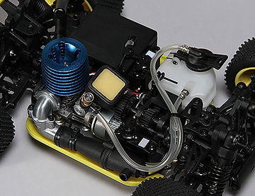
There's nowt like a good parcel I always say! Something of the Christmas/birthdays about it. This was waiting for me this lunchtime, and on first glance, the engine looks about perfect. I have to marvel at the rest of the vehicle as well, very nicely made, a masterpiece in plastic & aluminium! Even better is the fact that the motor is held in by 3 hex bolts underneath, then it's simply a case of disconnecting the throttle linkage and removing two plastic pipes.

Very easy to remove actually, 3 bolts or so, although I decided to keep the throttle linkage intact, as I may as well use the servo as well. Same goes for the plastic fuel tank, seems a shame to split the shebang up really.
So I plan to fit a 2mm aluminium engine pan, on to which I shall use the same bolts to mount both engine & tank, easy!
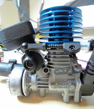
.07 ci of throbbing power! I've still no idea if this micro nitro will spin the wheels of my retro hairdryer, but we'll give it a go. It certainly looks the part. Cool blue head, luvvly air filter!

This is how it might look, insitu.

After a couple of attempts, (and driving my wife crazy with the noise of the hacksawing), I have two fork suspention guides. I'll just need to adjust the slots, depending on the dimensions of the metal I end up using.


I've also modified the rear number plate support, as it was annoying the hell out of me! I told you I was fussy.

The smell of rubber is now permeating through the house! Reminds me of the old cobbler's workshop that used to exist years ago in the backstreet's of good old MH. Reg Gibson, his name I believe. I used a spray adhesive to hold it down to the metal, seems to work fairly well.
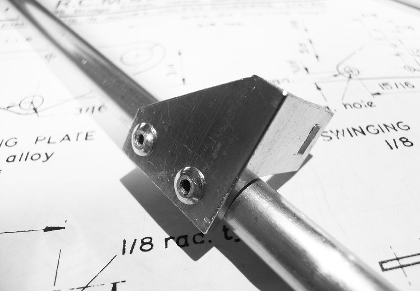
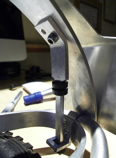
The steering column & bearing tube. J B specified a 'light alloy door bolt', but I had nothing like that, so I decided to make my own with some scrap 10mm tube & left over 3mm x 25mm flat bar and a length of 8mm carbon rod. I discovered that cutting the tubing with my plumbers pipe slice, whilst having the carbon insitu coincedentally made a good press fit for the top collar. Once the steering plates or yokes are assembled with the forks, I can slide the rod down and secure the bottom collar with a circlip.


Next up, is the belly pan. I'm still not certain about the final RC positioning, but I've decided to stick to JB's plan faithfully, that's kind of what this project is all about after all. I could have gone out and spent £300 on a 1/4 scale RC motorcycle from the likes of Buzzflyer if that was what I was after, no, that's definitely not what I'm after!
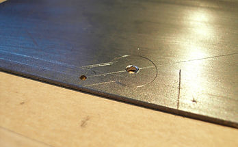
I had a little spare time today, (thank god for holidays) so apart from gazing wistfully out of the window on to the rain soaked landscape, I thought I'd knock up a 3mm aluminium motor mounting hole jig, and that's what I did ;-)
Actually, I'm glad I did this, as of course I managed to drill one hole slightly goofy, which is fine, as I managed to correct it, and it's far better to mess up at this stage, than when tackling the real thing, which should now be a simple case of fitting the cross member and positioning the jig and drill the mount holes, easy!
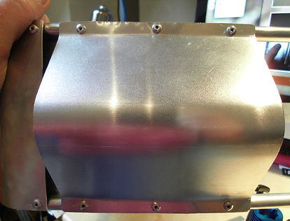
Belly pan riveted & complete. Just needs a polish, but it'll have to wait, as I've just just borked both my 'lightweight' dremel wire brush tools. :-(
I'm really excited about the latest arrivals. It came to me a couple of days ago, when I was talking about Buzzflyer and the bikes they sell. Although I wasn't interested in the bikes themselves (although I'm sure they're amazin' fun) I was interested in the spares! In particular the drive chain and sprockets. Well here they are, and not massively expensive (about £23 I think for the three parts). I must say, they look stunning. I've laid everything out dry, and have some ideas about how I'm goint to hold it all together. Although I am following JB's original plan faithfully, I'm not adverse to a little improvement of the model, if I may be so impudent? Well, it'll be identical to original in the theory, just modified to be adjustable, and I think, very sturdy and true.
Basically, I plan to mount the motor, and countershaft/swinging arm fulcrum all on one piece of metal. This will make it very rigid, but the mount holes will have slots, and so have a degree of lateral movement. The same will go for the rear wheel spindle mount as well. If you introduce chains into the equation, they are going to wear at some stage, and so cause issues with slackness. Also, I don't trust my drilling to be accurate enough!

I'm so impressed with this kit that it going to be a full width pic!
Here's how it's hangin' at present. I've hacked out a basic engine pan, and this will also be the mount for the countershaft brackets, which will in turn, bolt down on to this pan. I plan to have slots instead of fixing holes, to allow some lateral movement of the various parts, which should enable me to align everything nice and squarely, rather than rely on getting the holes 100% acurate first time, and as I say, as it's chain drive and also has gearing on the primary, the original drive belts JB used will not be around to soak up the innevitable inacuracies of my work!
So, I'm off for a little more forward planning and evening tv, hopefully my Hilka file set will arrrive tomoz, in which case, metal will be dressed!


Forward planning done! I've moved forward considerably I think, a couple of days good work, has certainly brought things to a stage. I bolted the front forks together using the cantilever pivot point, in readinesss for the epoxying of the fork yokes. I managed to drill the two holes through the forks and the 6mm studding, which enabled me to tighten the handlebars up, which went a good way to make things more solid. Then, in a two pronged attack, I turned my attentions to the engine mount.

I had a game with the engine mounting bolt holes, nothing serious, just a slight goofiness of one of the holes, despite bolting them all together in the fabricating process, the goofs creep in somehow! So after running the drill through a couple of times, I managed to get it all bolted down. I made the mistake of attempting to mount the tank, and made a bit of a mess to boot, but ho hum, I've figure out a better way to do it, and the holes will not be seen (I hope!).


Just dwelling on the forks for a moment (and why not? they took long enough to build!) It's a miracle I've managed to keep this thing square, without any kind of jig, pretty much by eye with the aid of a ageing set square. I know it's not high precision engineering or anything, but I figure with something based on two wheels, it's as well to get it as straight as can be, geometry wise at least. The only thing I may modify in time (if not now) is to use JB's original 6mm steering shaft and bronze bearings, as opposed to my 8mm carbon shaft and 'fit' in the aluminium tubing, as there is a little bit of play, which I don't altogether like. Having said that, it's not a real issue, I'm sure it'll be fine as it is, just the nagging prefectionist in me that's all!
Onward and upward...Some more drilling, hacksawing & filing, oh, and a measured dose of head scratching, and I think I have the countershaft just about where I want it :-)
I was a little stumped before, as was having to raise the gear wheel higher than I would like, which would have meant raisng up the 1" angle, which was goofy to say the least, so taking a step back, to go two forward was the better option. Now it's looking much better, and closer to the original spec.
Oh yes, it now has glow power onboard!


I've no idea how the real thing works, I think they have a gearbox and chain enclosed, but as I say, that's just a guess based on some vague rememberings of hairdryers parked outside my old local on occational evenings. Anyhow, it'll all end up enclosed behind the fibreglass side covers, so no worries, it's not scale. I guess I could have driven the rear wheel directly without the countershaft, but I would have had to adapt or remake the clutch bell housing to attach the pinion wheel, so I think I'm on the right track!
Last night, I spent an hour or so cutting the two countershaft bearing mounts, taking it steadily, then worked my way up the drills to arrive at the 12mm finished dia for the press fit bearings. I think it all went pretty well, and I offered the whole shooting match up to see how it was hanging. It was around about this point that I idly traced the direction of rotation of the motor pinion on the clutch housing, then reversing it onto the countershaft, reversing!
JB had of course used a system of drive pulleys, which do not reverse the direction of rotation! This would mean that my scooter would, in it's current configuration would be running backwards.
:-(
Woe is me! I hadn't even thought of this before, I had just taken it for granted. Doh!
So, how to put it right? Of course the answer is to reverse the engine 180 degrees, but the panic that ensued after my discovery blinded me to this solution, as I figured that the rotation would be the same whichever way it pointed, it was only later whilst studying the Turnigy 1/5th scale RC bike (which utilises a very similar gearing arrangement) that I saw their transverse engine was mounted in the other way, and indeed, it does indeed provide the correct rotation for the rear wheel!
Now I'm left with the practicalities of such a move, not a disater, but something I could obviously have done without. The easiest thing to do is for me to reverse the engine pan, by drilling the 6 rivets holding it down. I don't mind doing this, although if I get too many more rivet heads bobbing around inside the frame, it'll make more noise than an angry rattle snake!! And that's not good.
I don't think I really have too many options though, as modifying the pan with a slot on the other side and re drilling engine mount holes may weaken the mount too much, or at the very least will start to make it look a little bodged, which is not the required look.
Decisions decisions!
Another hickup with this discovery, was the fact that although the pull starter would now be in a better position pointing away from the drive mechanics, the exhaust manifold comes slap bang up against the countershaft, drat! My thoughts are to reconfigure the manifold, so it points upwards, which would clear the shaft, but would enter unknown territory vis-a-vis the running of the engine itelf. I was hoping to keep the geometry of the engine/exhaust/ tank & fuel feed as close to original as possible, for this very reason. Oh well, best laid plans and all that....


Another day, another dollar...Unbeleivebly, I seem to have made progress, slow, but progress none the less.
It seemed lately, that things have taken a downturn, maybe it's a heart not being in it thing, who knows, but whatever, I've more or less got the rear drive and swinging arm sorted, and today, at last, I've landed a couple of perfectly fitting wheel hubs for my antique tyres. The one you see above is the rear, a Firestone 6.00-16, and is now succesfully under aprox 20 psi of pressure! I had to dremel a little material from the hub, but basically, these toy/cart ebay wheels are the biz. I'm really pleased, asdespondancy had started to creep in to the quest for the elusive wheel hubs. :-(
Backtracking slightly, here's a pic of one of the countershaft bearing mounts, I still need to manipulate the left hand mount, as it's proving the very devil to get aligned correctly. I will prevail, failure is not asn option!
Some would call it a mess...

I call it 'home'
Another day at the office...Well, a fairly productive one anyway, and one that saw off some metal working demons that I semed to have been plagued with of late. I thought I'd focus on the rear end of the beast this evening, chiefly the suspention component, being a piece of 4mm aluminium scrap, that I shaped into something of beauty, well, not exactly beauty, but after an hour or so of fine filing duty, the swinging arm now moves up and down beautifully. I even added a couple of grommets top and bottom to limit and dampen the movement, ready for the 22 swg coil spring.
On a slight note of sadness, it appears at first glance, that I may not be able to use my Firestone tyre with inner tube after all, as it looks like being too big for the chassis. Bummer! well, if that's the case, then so be it, it'll be back on the Bay for another mooch around, and back on with the other. I'm not going to struggle with it, especially as the front tyre slots into the rear frame perfectly, being 10mm or so smaller on the dia. No inner tube in, but again, I can't afford to be too picky here, it's more important to get well fitting wheels/tyres than too much authenticity after all. My original build had some bad fitting components, leading to very sloppy suspension and geometry, making it hard to steer.
Rear suspension strut with dampers fitted
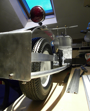
Here's the Firestone
(fits where it touches)
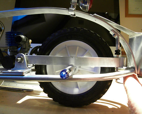
Here's the Kenning
(fits perfectly)

Well, good news (again) I've had another look at the Firestone rear tyre, and lo and behold, after a little air had been removed, it's game on again. It occurred to me today, but I hadn't realised the little amount of pressure I had added had increased the dia so much. It just goes to show how powerful pneumatic forces are!
Anyhow, on with the tale. To the left, you can see that I've made a start on the front suspention 'Spring guide', which is a piece of 1.5 mm mild steel. My axle will in fact be 7mm (threaded bar), so I've beefed up the axle hole by an extra mm, just in case, given that my drill/drilling is not the best.
Note to self: Remember to drill the holes before cutting the piece out!


So I wound a spring from 22 SWG piano wire, which brought back memories of the last time I wound my own springs, when I constructed some swinging door hinges from scratch a couple of decades ago. I felt that the gauge was to thin, so I ordered 4 1.5x10x100 mm springs from ebay, and when cut down to size, the rear is pretty much spot on. It may be a tad too stiff, but I guess only trial and error will tell.


Above you can see my effort on the left, not bad, but too thin. Here's the cheap torch I got of the 'bay too, with which I hope to silver solder the brash bushes on to the front spring guides & cantilevers.
At last! I'm so chuffed with these brass bushes, very simple, but a necessary jigsaw piece in my old school build. I must say a big thank you to a coleague of mine, named Will, who kindly and patiently reamed and chopped six of them off, cheers Will!


Well, although I ordered some silver soldering provisions from ebay at the princely cost of £3 odd, I've been thinking that I can't see why I couldn't solder these brass bushes using lead free solder that I use for soldering wires and components. After all, my iron reaches 480 degrees C after all.
So I cleaned the parts with emery paper, applied some flux, and heated the whole shebang up. after 10 or 15 seconds or so, the flux started to bubble, and shortly after, the solder started to flow, so I just moved the iron around the bush, and added solder as I went. It flowed very well, and soon I had enough on, so cut the heat.
The bush did move once or twice, but it was easy just to nudge it back centrally whilst hot.
Altogether, I'm extremely pleased with the results, now I have to reduce the hub width so the wheel fits betwen the bushes, nothing's easy on fettling st!
I suppose it may transpire that the lead (substitute) solder may not have enough strength, and may in time fracture under load, as it's quite soft, we'll see!


Well, the net effect is to give greater clearance for the tyre at the top. Also, my experiment with moving the cantilever arms back. has not yielded the results I would have liked. It does give greater movement/travel of the suspension arm, but appears to introduces an extra degree of play on the axle and suspension memebers themselves, due to the increased distance of the axle to the cantilever pivot. It looks as if I will need to put it back as it is, then trim off one of the surplus holes on the end of the cantilever to clear the tyre.
I'm also on the hunt for a 3mm metric tap, as I think I will need to add a grub screw to the bottom brass bearings of the spring guides, as was intended on the original plan, to lock the axle as a tortion bar.

The front suspention and axle components assembled. I've added some mods as I went along, like soldering the bottom spring retainer to a 7mm ID washer, so the spring sits squarely, and slightly tensioned and captivated.
I may do something similar at the top, I'm thinking brass cup washers, can I get them big enough...?
I've been looking at the clearances vis-a-vis the front wheel/tyre and the suspension parts, and decided that the top spring guides could be improved. So to that end, I drilled/filed two new slots, farther out than before. When I had done it, I was worried that there would not be enough clearance with the outer edge of the guide. I negated this slightly, by bending the spring guide inward slightly as it passes through the slot. Then, I noticed that because of the reduced clearance, it was no longer possible to use a pin through the guide as a down limiter. I was begining to think I may have done the wrong thing here, but I think I can self tap the 1mm holes to accept a small hex head bolt, which will do the job nicely. Here's hoping!

This pic shows the rake of the spring guide in the second pivot hole of the cantilever. It actually works quite well, so just needs a screw fitting to the top of the spring guide down-limit hole, and a grub screw placing on both of the spring guide bottom bushes. I think you can clearly see the extra clearance now at the top, between the spring guide brackets.
All I can do, is finish off these little tasks, and then see if this rake works, or if it is indeed too loose for comfort. It does feel remarkably strong, so far, and becomes more roadworthy with every completed stage. Hark!, I can almost hear the Who tuning up in the distance...
Since my last post, I did go back and reconfigure the rake of the suspension arm, opting in the end for the original position, parallel with the forks. Now I've tightened up the axle, and added the grub screws (how satisfying it is to tap a screw hole? I pity those who have never done it) it works really nicely and quite smooth in operation.
I also spent a little time with the limit pins on the spring guides. I have settled on a 2mm hex bolt in each, and I managed to self tap them into the arms! The grub screws turned out very easy to do in the end, using a 4mm tap.
Well, it's been a while!
What with one thing and another, mainly flying model multirotor's, I've had little time to advance the project. I glanced at it the other day, and it started calling to me to finish it off!
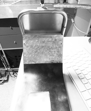
So I decided to hone my skills further with the 2D design package I have at my disposal, and create/cut the seat base from 6mm balsa. I didn't question the material off the plan, but it does seem a tad flimsy, although there will be little weight on it as such, I hope it supports the leather ok, without warping! JB used nylon to cover his seat with, which is obviously more flexible and light.

I've had the idea to epoxy a strip of 3mm aluminium along the length of the seat to tap into for the mountings, which in turn will strengthen the base.
Also, it occured to me, that if I cut a thin piece of material to the same dimensions, it would sandwich the leather material, and make the whole thing much more secure. If I had acces to a cnc mill, I would use aluminium, which could be beaded on the edge and polished, to look like a seat bezel!
Oh well, worth a thought.
What with one thing or another, I haven't been able to give the project much quality time since the back end of last summer, but now (January 2015) I've had a resurgence of interest, and have managed, at last, to make some gentle progress! I think the daunting task of the last major 'engineering' bit had hindered me, and prevaracation had become the word of the day.
The seat, although integral to the finished project in itself, can wait until I have a model that pretty much works, and on that basis, I set about fabricating and fitting the rear wheel and it's associated parts, namely a working brake, and the chain-set.
I had already sourced the parts required for the task, the rear chainwheel and chain from Buzzflyer (from their 1/4 scale RC motorbike spares catalogue) and Hobby King for the brake and another shorter chain and smaller rear sprocket. I notice that HK themselves now stock the 1/4 scale electric motorcross bike, complete with inbuilt gyro for the rear wheel and RC gear to boot. Its price of £174 made me wonder momentarily if I was doing the right thing by cobbling this together myself, but after all, it's not really about buying something off the shelf, but a labour of love.
So, on with the show! The first pic

showing the brake disk caliper unit close-up. It was fairly easy to incorporate it into my wheel assembly, it just needed holding centrally, then I drilled and tapped a couple of 3mm holes into the plastic hub, which held it nicely.
I'd already fitted the hub with bearings last year, and the whole axle is just simply a piece of 7mm threaded bar cut to length. It's an odd size, being rarely used in engineering, the exceptions being the exhaust studs on Lambretta motor scooters (ironically) and I think Volkswagon used them somewhere on the Beetle. I used nylocs to hold it all together, and they worked well, doubling up as spacers. All in all, the rear arm assembly and suspension components are working together very nicely, and I have to say 100% better than my earlier attempts!
Here you can see how it's hanging. You can see the countershaft in the background, the end of which is where I was planning to add a pinion wheel for a short drive belt & electric motor for my 'hybrid' idea, but I'm straying from that idea a little in favour of a more conventional approach.


With every silver lining there is a cloud! This particular cloud came in the form of an issue with clearance of the chain, where it passes the tyre. There simply wasn't enough! So I agonised about modifications. There appeared to be more room the other side, but when I reversed things, there was nothing really in it, so I put things back and thought about it for a while. As with most things in life, there are always several ways of achieving a certain goal, and the more I stared at the problem, the more I figured a less 'surgical' solution would be best. So I got straight back on my old friend ebay, and chased down a couple more ashtray tyres from somebody's loft, and I am, as, as I write, awaiting their arrival.
Im hoping that one of them at least will be of a narrower profile, but the photo's left a little to be desired, so it really is a case of wait and see!
The chain is a little loose too, despite rtemoving a link, obviously the real thing has some degree of adjustment, which mine currently lacks. I considered adding a tensioner wheel, but in the end, I'll likely opt for a modified hub mounting which incorporates some latreral movement. It will actally run as it is, but we all know what happens when the chain gets too lose!

As an aside, I had another look at my steering column setup, although it all looked nice, it had too much free play for my liking, and could have potentially made the steering a bit 'loose'. The shaft was a piece of 8mm carbon, another thing I wasn't entirely happy with. Ideally the tube would have a couple of bearings, top and bottom, but I figured that was a bridge too far, and instead, opted for my old friend, the threaded bar. I've locked it all down with thin nuts, and ideally I would source an 8mm hub nut to cap it off more aesthetically, like the fork nuts.
I also managed to produce a reasonable 22swg wire spring for the steering mechanism, and appears to do the job. I notice the modern day equivalent R/C bikes use amore rigid connection for the servo, which incorporates a spring for strain relief.
I'm not certain if JB designed his ingenious steering system expressly to cope with limitations of 'bang bang' radio control systems, as oposed to the more expensive 'digital proportional' radio's like Futaba or Kraft, but of course with the plethora of sophisticated R/C gear available today (for no money at all) there are bags more options for control of these things. If you can think of it, it can be done!
4th March 2015
Well, my tyres arrived from ebay, and I couldn't have asked for a better fit! In fact, as the second 'bonus' tyre was a nice soft variety, I decided to swap out both tyres.
As you can see, the rear tyre was indeed a feew mm narrower, and as such clears the chain with ease.
After a few thoughts regarding the chain tension, I simply elongated the wheel mounting hanger mount holes to all;ow some lateral movement. This also ironed out the slight vertical tilt of the rear wheel.
Overall, I'm very happy with how the rear wheel mounting has come together, as it was really the last major engineering challenge.
Apart from some fiddly stuff like sowing the leather for the seat, and fabricating the side covers, all the running gear is now complete.

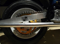


Close up of the rear chain sprocket, and above, the tank has now been mounted!